Where no faults are present, lubrication prevents the metal surfaces from contacting and no stresswaves are produced, however, when the lubrication is insufficient, metal to metal contact produces stresswaves.
As a fault develops in a bearing, we will see the stresswaves, and if the forces are great enough, we will also see resonance of one or more of the bearing components.
The contact between two surfaces produces a shock or pressure wave that radiates away from the source at very high speed. By understanding these high frequency, often low amplitude, short duration events we can identify the cause of the vibration, understand the severity of the fault and decide on a suitable course of action.
Demodulation / Enveloping and Peakvue are two of the most common methods used throughout industry to allow for effective analysis of these signals by manipulating the high frequency signals and making them available as a lower frequency, easier to interpret displays.
Why do we collect enveloping or stresswave data during vibration analysis?
For many years Enveloping (also known as Demodulation) has been a standard detection technique for the detection of the following:
- Bearing Lubrication Issues
- Bearing Defects
- Gear Defects
- High frequency impacts causing ‘high frequency resonance’ of components (e.g. bearing outer raceway)
There are limitations with the capabilities of Enveloping/Demodulation Techniques due to the applied mathematical algorithm however, this is mitigated with the development of Stresswave detection techniques. Table 1 shows capability comparisons between the two techniques.
Table 1 – Enveloping vs Stresswave Detection capability comparisons
| Enveloping/Demodulation |
Stresswave/Peakvue |
| Analogue Processing |
Analogue and Digital Processing |
| Lower Sampling Rate |
>100kHz Sampling Rate |
| Typically Good Frequency Detection |
Consistently Good Frequency Detection |
| No Reliable Amplitude Measurement |
Accurate and Trendable Amplitude |
| Spectral Output Only |
Spectral and Waveform Output |
How do both processes work?
Fundamentally both techniques are designed to serve the same purpose and output requirements. As with any applied process understanding the benefits, limitations and capabilities is key to success. Due a very high frequency of sampling Stresswave detection has the ability to detect very short duration low amplitude impacts caused by very early stage bearing wear. Due to delays in the analogue filtering within demodulation the ability to detect the peak and the methods of calculation these early warning signs can be missed or averaged out of the signal during processing.
Figure 1 shows a typically impactive waveform caused by early stage bearing defects on slow speed machinery. Stresswave detection is an industry leading technique for detection of faults at very low shaft RPM’s where enveloping may miss the defect.

Figure 1 – Waveform Registration Comparisons
This delay in the envelope processing can lead to loss of data during calculation in both low speed and high speed applications. For example Figure 2 shows the tendency of enveloping techniques to not register the defects when monitoring high speed machinery usually above 3600rpm shaft speed.
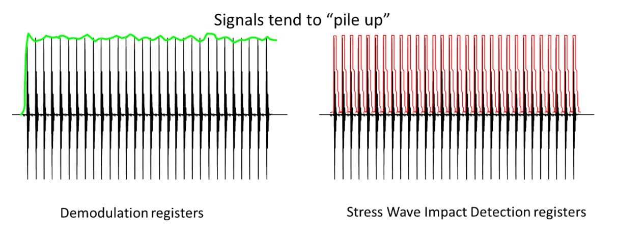
Figure 2 – Waveform Registration Comparisons on high speed machinery
Figure 3 shows a comparison of data collected from the same machine with the same fault at different filter settings showing clarity of results when utilising Stresswave detection techniques.
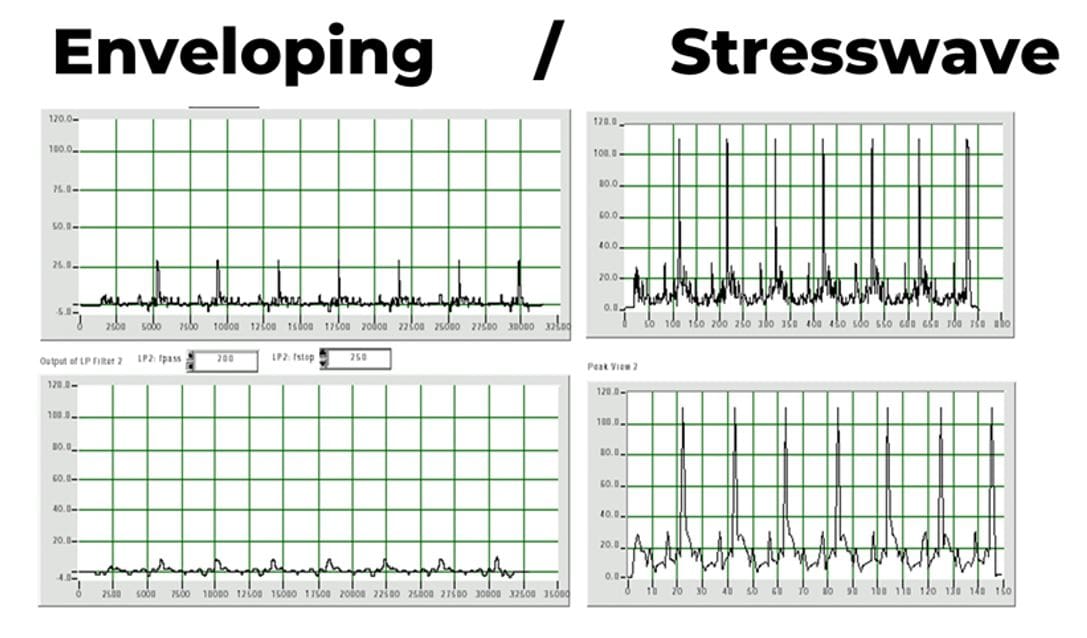
Figure 3 – Waveform comparisons (Envelope – Left, Peakvue/Stresswave – Right)
What are the benefits of stresswave detection?
The primary purpose of these detection techniques is to prevent failure and mitigate the root causes for the failure modes. Enveloping techniques are able to detect similar faults however, the lack of trendability of the results can lead to misdiagnosis of the fault and misinterpretation of the severity leading to increased failure risk.
The Stresswave detection techniques provide the earliest indication of bearing, gear, and other metallic contact faults due to the processing methods following development of monitoring hardware and software. As this can be trended the rate of change can be understood to ensure the requirement of maintenance intervention is understood.
Figure 4 shows the typical P-F curve of a rolling element bearing failure pattern and whereby Stresswave provides the earliest indication of bearing deterioration.
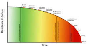
Figure 4 – Typical Rolling Element Bearing P-F Curve